Chapter 6
Component diagrams

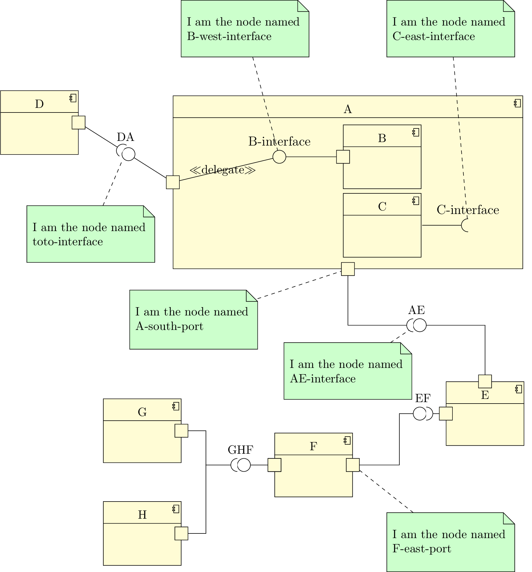
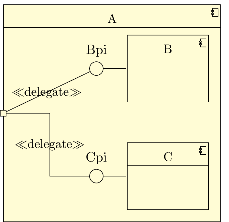
Here is an example of component diagram you can draw:

pict

Now, we will talk about elements that compose such diagrams:

6.1 To define a component

A component can be defined with the umlcomponent environment:

 \begin{tikzpicture}  \begin{umlcomponent}[x=0,y=0]{A}    \end{umlcomponent}  \end{tikzpicture}

pict

Both options x and y allow to place the component in the figure, or in another component. The default value is 0. The argument to give is the label of the component. The node representing the state has a default name, based on a global counter. For practical reasons, you can rename it with the name option.

You can also define the width of an empty component with the width option (8ex by default).

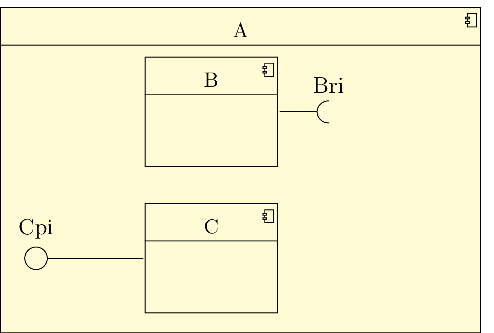
You can define a component in another component or in a package. Then, the coordinates of the sub-component are relative to the parent component or package:

 \begin{tikzpicture}  \begin{umlpackage}{p}  \begin{umlcomponent}{A}  \begin{umlcomponent}{B}  \umlemptyclass{D}  \end{umlcomponent}  \begin{umlcomponent}[x=4,y=-2]{C}    \end{umlcomponent}  \end{umlcomponent}  \end{umlpackage}  \end{tikzpicture}

pict

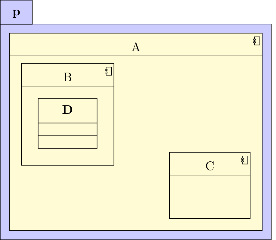
Notice that you can define a class inside a component.

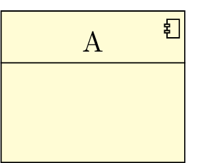
If you want to define a component without detailing it, you can use the umlbasiccomponent command, that is an alias of the umlcomponent environment.

Every TikZ option dedicated to nodes can be used here, see section 2.5 for details.

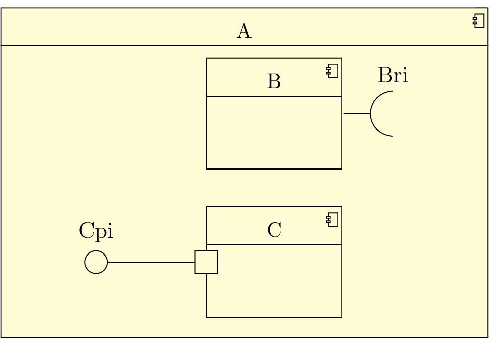
6.2 To define a provided/required interface

On a component, you can define 2 kinds of interfaces: provided interfaces and required interfaces. For that purpose, you can use umlprovidedinterface and/or umlrequiredinterface commands. These 2 commands offers the same list of options:

 \begin{tikzpicture}  \begin{umlcomponent}{A}  \umlbasiccomponent{B}  \umlbasiccomponent[y=-2.5]{C}  \umlrequiredinterface[interface=Bri,distance=2cm, width=2em]{B}  \umlprovidedinterface[interface=Cpi,distance=3cm, with port]{C}  \end{umlcomponent}  \end{tikzpicture}

pict

The interface option is used to give the label of the interface, written above the interface symbol. The interface symbol is a node named X-Y-interface, where X is the name of the component, and Y is west for a provided interface and east for a required interface.

You can change these default names with the name option.

The width option is used to size the interface symbol. The default value is 1em.

The distance option is used to set the distance between the interface symbol and the component port.

The with port option is used to draw the port symbol.

If you look at the previous example, you can notice the padding between the interface symbols on sub-components, and the boundary of the parent component. You can change it with the padding option. The default value is 1cm.

 \begin{tikzpicture}  \begin{umlcomponent}{A}  \umlbasiccomponent{B}  \umlbasiccomponent[y=-2.5]{C}  \umlrequiredinterface[interface=Bri,distance=2cm, padding=2cm]{B}  \umlprovidedinterface[interface=Cpi,distance=3cm, padding=0cm]{C}  \end{umlcomponent}  \end{tikzpicture}

pict

This option will be very useful when you draw connectors, as you will see in the next section.

6.3 To define an assembly connector

An assembly connector is a relation between 2 different components. It is graphically the provided interface of one of them with the required interface of the other. For that purpose, you can use the umlassemblyconnector command:

 \begin{tikzpicture}  \umlbasiccomponent{A}  \umlbasiccomponent[x=4, y=-2]{B}  \umlassemblyconnector[interface=AB]{A}{B}  \umlHVassemblyconnector[with port]{A}{B}  \end{tikzpicture}

pict

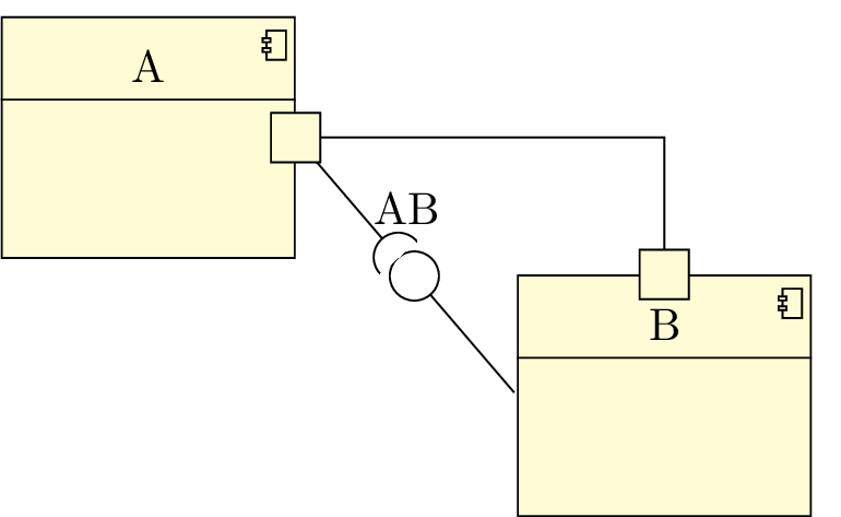
The assembly connector symbol is drawn only if the interface option is given. As for umlprovidedinterface and umlrequiredinterface commands, the with port option is used to draw ports, and the width option is used to set the size of the assembly connector symbol (default is 1em).

You can also name the assembly connector with the option name.

6.3.1 To define the geometry of an assembly connector

As for umlrelation command, you can use the geometry option and shortcuts are defined:

umlHVassemblyconnector:
shortcut of umlassemblyconnector with geometry=-|
umlVHassemblyconnector:
shortcut of umlassemblyconnector with geometry=|-
umlHVHassemblyconnector:
shortcut of umlassemblyconnector with geometry=-|-
umlVHVassemblyconnector:
shortcut of umlassemblyconnector with geometry=|-|

6.3.2 To place the assembly connector symbol

To place the assembly connector symbol, you can use the first arm, second arm, middle arm or last arm options:

 \begin{tikzpicture}  \umlbasiccomponent{A}  \umlbasiccomponent[x=4, y=-3]{B}  \umlHVHassemblyconnector[interface=AB1, arm1=6cm, last arm]{A}{B}  \umlHVHassemblyconnector[interface=AB2]{A}{B}  \umlVHassemblyconnector[interface=AB3, first arm]{A}{B}  \end{tikzpicture}

pict

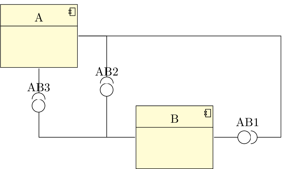
6.3.3 To adjust the geometry of an assembly connector

As for umlrelation command, you can use the arm1, arm2, anchor1, anchor2 and anchors options:

 \begin{tikzpicture}  \umlbasiccomponent{A}  \umlbasiccomponent[x=4, y=-3]{B}  \umlHVHassemblyconnector[interface=AB1, arm1=6cm, anchor1=20, last arm, with port]{A}{B}  \umlHVHassemblyconnector[interface=AB2, anchors=-20 and 160, arm2=-0.5cm]{A}{B}  \umlVHassemblyconnector[interface=AB3, first arm, anchor2=-160]{A}{B}  \end{tikzpicture}

pict

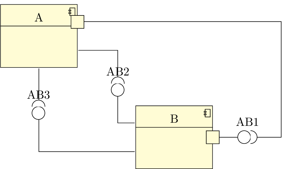
The position of the ports is automatically evaluated according to the values given to these options and to the geometry option.

6.4 To define a delegate connector

A delegate connector is a connector between a sub-component and its parent component. For this purpose, you can use the umldelegateconnector command. It has all options of umlrelation command except stereo, that is set to delegate.

 \begin{tikzpicture}  \begin{umlcomponent}{A}  \umlbasiccomponent{B}  \umlbasiccomponent[y=-3]{C}    \umlprovidedinterface[interface=Bpi, distance=2cm, padding=2cm]{B}  \umlprovidedinterface[interface=Cpi, distance=2cm, padding=2cm]{C}  \end{umlcomponent}    \umldelegateconnector{A-west-port}{B-west-interface}  \umlHVHdelegateconnector[pos stereo=1.5]{A-west-port}{C-west-interface}  \umlport{A}{west}  \end{tikzpicture}

pict

6.5 To define a port on a component

Sometimes, as in the previous example, you have to draw manually a port. For this purpose, you can use the umlport command.

The first argument is the component name, the second one is the anchor of the component node where you want to draw the port. You can set the size of the port with the width option.

6.6 To change preferences

Thanks to the tikzumlset command, you can set colors for components, provided/required interfaces, ports and assembly/delegate connectors:

text:
allows to set the text color (=black by default),
draw:
allows to set the color od edges and arrows (=black by default),
fill component:
allows to set the background color of components (=yellow !20 by default),
fill port:
allows to set the background color of ports (=yellow !20 by default),
fill assembly connector:
allows to set the background color for assembly connector symbols (=white by default),
font:
allows to set the font style (=\small by default).

You can also use the options text, draw and fill on a particular element.

There is an exception: umlassemblyconnector. The option fill assembly connector sets the colors of the assembly connector symbol, whereas the option fill port sets the colors of the port symbol.

6.7 Examples

6.7.1 Example from introduction, step by step

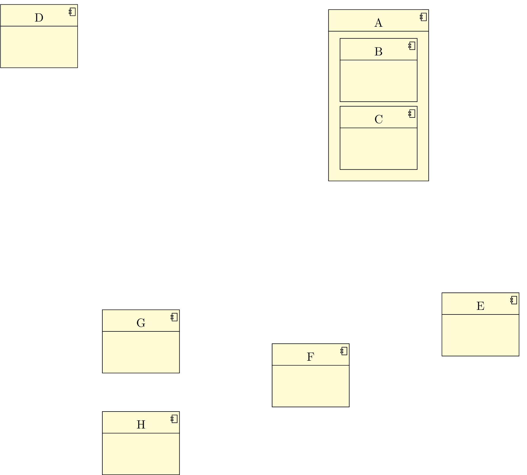
Definition of the components

There is 6 components A, D, E, F, G and H, and 2 sub-components of A: B and C.

 \begin{tikzpicture}  \begin{umlcomponent}{A}  \umlbasiccomponent{B}  \umlbasiccomponent[y=-2]{C}  \end{umlcomponent}  \umlbasiccomponent[x=-10,y=1]{D}  \umlbasiccomponent[x=3,y=-7.5]{E}  \umlbasiccomponent[x=-2, y=-9]{F}  \umlbasiccomponent[x=-7,y=-8]{G}  \umlbasiccomponent[x=-7,y=-11]{H}  \end{tikzpicture}

pict

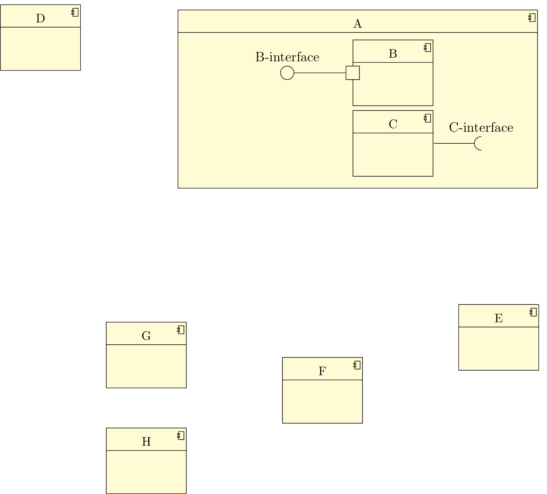
Definition of the interfaces

We define a required interface for the component B, and a provided interface for the component C. We prepare the delegate connector by setting the padding.

 \begin{tikzpicture}  \begin{umlcomponent}{A}  \umlbasiccomponent{B}  \umlbasiccomponent[y=-2]{C}
 \umlrequiredinterface[interface=C-interface]{C}  \umlprovidedinterface[interface=B-interface, with port, distance=3cm, padding=2.5cm]{B}
 \end{umlcomponent}  \umlbasiccomponent[x=-10,y=1]{D}  \umlbasiccomponent[x=3,y=-7.5]{E}  \umlbasiccomponent[x=-2, y=-9]{F}  \umlbasiccomponent[x=-7,y=-8]{G}  \umlbasiccomponent[x=-7,y=-11]{H}    \end{tikzpicture}

pict

Definition of the connectors

We define 5 assembly connectors and 1 delegate connector.

 \begin{tikzpicture}  \begin{umlcomponent}{A}  \umlbasiccomponent{B}  \umlbasiccomponent[y=-2]{C}    \umlrequiredinterface[interface=C-interface]{C}  \umlprovidedinterface[interface=B-interface, with port, distance=3cm, padding=2.5cm]{B}  \end{umlcomponent}  \umlbasiccomponent[x=-10,y=1]{D}  \umlbasiccomponent[x=3,y=-7.5]{E}  \umlbasiccomponent[x=-2, y=-9]{F}  \umlbasiccomponent[x=-7,y=-8]{G}  \umlbasiccomponent[x=-7,y=-11]{H}
   \umlassemblyconnector[interface=DA, with port, name=toto]{D}{A}  \umldelegateconnector{A-west-port}{B-west-interface}  \umlVHVassemblyconnector[interface=AE, with port]{A}{E}  \umlHVHassemblyconnector[interface=EF, with port, first arm]{E}{F}  \umlHVHassemblyconnector[interface=GHF, with port, arm2=-2cm, last arm]{G}{F}  \umlHVHassemblyconnector[with port, arm2=-2cm, last arm]{H}{F}  \end{tikzpicture}

pict

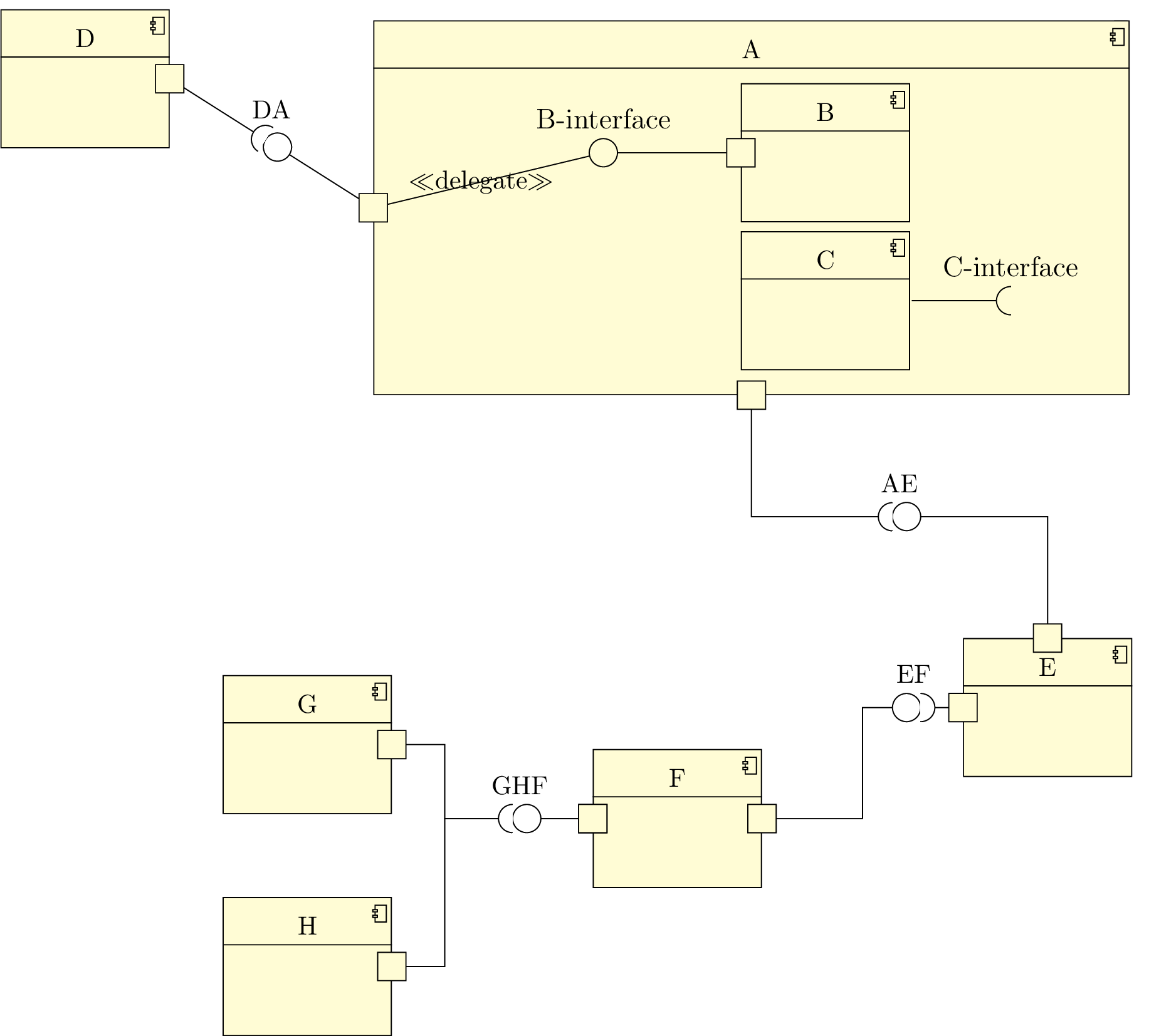
Definition of the notes

We add notes to explain the node names.

 \begin{tikzpicture}  \begin{umlcomponent}{A}  \umlbasiccomponent{B}  \umlbasiccomponent[y=-2]{C}    \umlrequiredinterface[interface=C-interface]{C}  \umlprovidedinterface[interface=B-interface, with port, distance=3cm, padding=2.5cm]{B}  \end{umlcomponent}  \umlbasiccomponent[x=-10,y=1]{D}  \umlbasiccomponent[x=3,y=-7.5]{E}  \umlbasiccomponent[x=-2, y=-9]{F}  \umlbasiccomponent[x=-7,y=-8]{G}  \umlbasiccomponent[x=-7,y=-11]{H}    \umlassemblyconnector[interface=DA, with port, name=toto]{D}{A}  \umldelegateconnector{A-west-port}{B-west-interface}  \umlVHVassemblyconnector[interface=AE, with port]{A}{E}  \umlHVHassemblyconnector[interface=EF, with port, first arm]{E}{F}  \umlHVHassemblyconnector[interface=GHF, with port, arm2=-2cm, last arm]{G}{F}  \umlHVHassemblyconnector[with port, arm2=-2cm, last arm]{H}{F}
   \umlnote[x=-4, y=4, width=3.4cm]{B-west-interface}{I am the node named B-west-interface}  \umlnote[x=2, y=4, width=3.4cm]{C-east-interface}{I am the node named C-east-interface}  \umlnote[x=-8.5, y=-2, width=3.4cm]{toto-interface}{I am the node named toto-interface}  \umlnote[x=-5.5, y=-4.5, width=3.4cm]{A-south-port}{I am the node named A-south-port}  \umlnote[x=-1, y=-6, width=3.4cm]{AE-interface}{I am the node named AE-interface}  \umlnote[x=2, y=-11, width=3.4cm]{F-east-port}{I am the node named F-east-port}  \end{tikzpicture}

pict